The PSMA Core Loss studies have their roots in frustration with the traditional core loss estimations.
1. There is no need to use the unfamiliar magnetic parameters. Core loss calculations can use voltage, current and time.
2. For a magnetic component, there is no need to use dimensional factors, any more than one would buy a resistor using the resistivity and dimensions of its core.
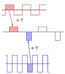
3. Most core loss data is taken with sine-wave excitation, but most power converters use rectangular excitation, often with reduced duty-ratio.
A hypothesis, later dubbed the "Composite Waveform Hypothesis" proposed that the core loss with low duty-ratio rectangular excitation could be derived from square-wave data.
For more information, see User-friendly Data for Magnetic Core Loss Calculations, Edward Herbert, Canton, CT. November 10, 2008.
Dartmouth Study -- Pilot Project
The Pilot Project was approved by PSMA and a purchase order to Dartmouth was issued in the Spring of 2009. Data was taken on one ferrite core and one powdered metal core. The composite waveform hypothesis was partly validated, and shown to be an improvement over other approximations, both for accuracy and for ease of use. However, it was observed that increasing off-time between excitation pulses increased the loss per cycle.
For more information, see Testing Core Loss for Rectangular Waveforms, February 7, 2010 by Charles R. Sullivan and John H. Harris, Thayer School of Engineering at Dartmouth and Edward Herbert.
The Pilot Project data can be downloaded from http://www.psma.com/coreloss/pilot
Jonas Mühlethaler's paper
Jonas' paper was not sponsored by PSMA, but it is mentioned here because it is an important contribution to the study of the "off-time phenomenon." The importance of this paper is that it confirmed the off-time loss using a different core on different test apparatus. Jonas identified two off-time loss mechanisms, a "relaxation phenomenon" that has a fairly short time constant immediately following turn-off, and a longer effect due to circuit impedance.
See: Improved Core Loss Calculation for Magnetic Components Employed in Power Electronic Systems, Muhlethaler, J.; Biela , J.; Kolar , J. W.; Ecklebe , A.; Power Electronic Systems Laboratory, Zurich, Switzerland
Dartmouth Study -- Phase II Project
The Phase II Project was approved by PSMA and a purchase order to Dartmouth was issued in the Spring of 2010. The Phase II project had two principle objectives:
1. To test the composite waveform hypothesis on a variety of cores of different materials, with emphasis on ensuring that the off-time loss phenomenon was not just a test rig or test procedure artifact.
2. To test a core that had been drilled through with sense windings installed, to see if flux migration may contribute to the off-time loss phenomenon.
The Phase II study confirmed that the off-time phenomenon is seen on a variety of cores of different shape and material. Flux migration is seen in the drilled core experiments, but its timing and magnitude suggests that it is not an important factor in the off-time losses.
There were several important by-products of the study:
1. The Dartmouth team developed a "hippo waveform" as a test excitation. A pulse of one polarity is immediately followed by a pulse of the opposite polarity and the same pulse width, followed by an off-time. The current returns nearly to zero during the off-time. This may be the most important achievement of the Phase II Project. It is unlikely that the hippo waveform will be used in practical power converter circuits, but its use for testing will be invaluable.
2. Dr. Sullivan applied square wave data to a Steinmetz-like equation for estimating core losses. Unlike the traditional Steinmetz equations for sine wave data, one set of parameters can be used over a very wide range of voltages and pulse widths.
3. Dr. Sullivan analyzed Fourier expansion and its applicability to core losses. He showed that core loss of non-sinusoidal waveforms cannot be accurately predicted by separately examining the Fourier components of the waveform.
For more information, see Testing Core Loss for Rectangular Waveforms, Phase II Final Report, 21 September 2011 by Charles R. Sullivan and John H.Harris; Thayer School of Engineering at Dartmouth.
The Phase II Project data can be downloaded from http://www.psma.com/coreloss/phase2
Phase II Supplemental Report
The Pilot Project and the Phase II Project took massive amounts of data, far more than could be analyzed under the Phase II time and budget constraints. Accordingly, a supplemental report was undertaken to see if additional information could be extracted from the data. The raw data of the Pilot Project and the Phase II data were used. Fortunately, they are of the same format and file structure, so one set of tools could examine all of the data. See A Supplemental Report, Edward Herbert, Co-chairman, PSMA Magnetics Committee, December 14, 2011. This supplement is a work in progress and may be revised from time to time.
It is hoped that others will use the data to further the study of core losses. The data can be downloaded using the links above.
If others would like to contribute to this web page, their input is welcome.
Tools
A number of tools were developed for accessing, analyzing and presenting the data. Links to the tools and directions for using them are in the Supplemental Report
Selected data files
A number of special data files were used in preparing the Supplemental Report. These are data derived from the raw data but are sorted and otherwise edited to extract specific information. Links and instructions for using them are in the Supplemental Report..
Conclusions
The conclusions of the Supplemental Report are summarized here:
1. Increased off-time does increase the energy loss per cycle, but mostly the off-time provides a window of opportunity to see and identify some loss factors while other loss factors are reduced or absent.
2. The test circuit and protocol can influence losses, including off-time losses. However, these influences are present in practical circuits as well, and they need to be identified and quantified. It is therefore not valid to dismiss them as "test rig artifacts."
3. Energy going into a magnetic core is divided between "burned energy" and "stored energy." Separating them is daunting.
a. Burned energy (dissipated, as in resistance) probably can be quantified quite well (but not entirely) using the composite waveform hypothesis.
b. Stored energy (stored in inductive reactance, as in ½ I2L) that is carried forward to the next pulse reduces the net input current and thus the input power and the energy lost per cycle.
c. The loss of stored energy significantly influences core losses. It is attributable to the core characteristics (delayed burned energy); the external circuit (or test rig); and the test protocol (waveform).
d. Some losses may be impulses or spikes, at the switching time, and thus are analogous to switching losses.
e. Stored energy loss is particularly difficult to quantify in a simple expression. It is unlikely to be quantifiable as a material characteristic.
4. Determining the stored energy carried forward from pulse to pulse and the loss of that stored energy is essential to improving the estimation of core loss and improving circuit performance.
5. Equations such as the familiar Steinmetz equation and its many enhancements become complicated to the extent that their general use is unlikely. At least five loss mechanisms must be accounted for as well as the influences of the external circuit and waveform.
6. It must be concluded that the composite waveform hypothesis is a failure, at least as applied to high frequency core losses. That it compares well with other models is pointless if its results have large errors at low duty-ratio.
7. Using the "hippo" waveform to analyze core losses may be the most significant accomplishment of the Phase II project. The hippo waveform is unlikely to be used for practical power converters, but its use for analysis is brilliant.
8. The most promising way to characterize core losses may be as an impedance.
9. Characterizing a specific core or a specific wound component is better (more accurate, easier to use) than characterizing a material.
10. An impedance model can be used for improved SPICE simulations.
A working hypothesis is that if the hysteresis loop can be faithfully reproduced using an impedance model for various waveforms, the loss estimations will be as good as the match of the areas within the hysteresis loops. Because a very important factor is the stored energy and its loss, faithfully reproducing the current during the off time of low duty-ratio waveforms is important.
Impedance models are familiar turf for an electrical engineer. Measuring them is fundamental to circuit analysis. Quantifying them both in the time and frequency domain is fundamental to stability analysis. Synthesizing them is fundamental to the design of filters and compensation networks. This expertise can be applied to modeling the magnetic core. Overkill should be avoided. A simple model may suffice for most applications.
One must not lose track of the fact that a model is an analogy. It may not reveal much about the physics of what is happening in the core.
Dartmouth Study -- Phase III Project
The Phase III Project was approved by PSMA and a purchase order to Dartmouth was issued in the Spring of 2012. The Phase III project had several objectives, but due to equipment problems and the loss of key personnel, very few meaningful tests were run.
Most of the test time was used debugging and modifying the test equipment. Some tests were run to see if the test rig influenced the test results. No important influence was found, but some of the planned tests were never run. These activities did not really advance the understanding of core losses, so they are not analyzed further. Those interested in this activity can find it in the Dartmouth Phase III report.
See PSMA Magnetics Committee Core Loss, Phase III Final Report, 20 March, 2013 by John H.Harris; Thayer School of Engineering at Dartmouth.
The data from Phase III are in the same format as the earlier phases, so all of the tools for calculations and plotting of graphs described in the Phase II Supplemental Report are usable. The Phase III data can be found at http://www.psma.com/core-loss-studies/phase3.
Phase III Supplemental Report
One group of the Phase III tests was planned to explored alternative winding configurations. Many of the planned tests were not run, but one that was done showed some interesting effects. Unfortunately, only three test runs were run, one as a baseline and two experiments. With so little data, the results are suggestive but cannot be considered conclusive.
A string of small cores having one turn through all can be designed to have the same inductance and core volume as a single toroid having multiple turns, in this case, five turns. A rigorous test would require specially machined cores, but an approximation was tested using stock cores. The test results and some speculation can be found in Phase III Supplemental Report: The String of Beads Experiment by Edward Herbert.
Edward Herbert
Co-Chairman, PSMA Magnetics Committee
Revised 16 December, 2013
