 ver the past five years, the PSMA Magnetics Committee has sponsored five Special Projects to better understand the flux propagation in ferrites and the reasons why the performance of large inductor cores performed so poorly compared to the expectations based on published specifications from the suppliers.
The first three projects - PSMA -Dartmouth Core Loss studies- were undertaken by Dartmouth under the leadership of Professor Charles Sullivan and the results are available on the Magnetics Forum on the PSMA web site. Based on some of the insights from these projects formed the basis for the 2 most recent projects – PSMA- SMA Core Loss Studies Phase 1 and Phase 2.
The last two Core Loss Studies are now complete, and this article highlights some of the most interesting findings. This article is not as comprehensive as the reports, and the reader is encouraged to read the full reports on the PSMA web site for more information.
PSMA–SMA Core Loss Study Collaboration
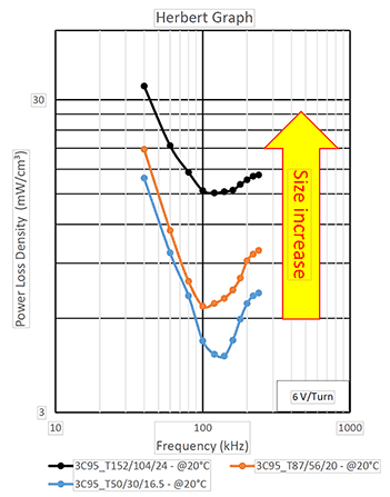
SMA Magnetics was interested in why large inductor cores performed so poorly compared to expectations based upon published specifications. At the the same time, PSMA was interested in flux propagation in ferrites and why the performance factor B*f was lower and peaked at a lower frequency for larger cores.
Charlie Sullivan (Dartmouth) recognized that there was significant overlap in these interests and arranged an introduction which resulted in the Phase I PSMA-SMA core Loss study. The findings of the Phase I study were so intriguing that a Phase II study followed, which built upon the data from Phase I.
The Phase I and Phase II test reports can be found on the PSMA website Core Loss Studies tab of the Magnetics Forum. The Phase I report is publicly available; Phase II is currently only available to PSMA members, and will be publicly available in late 2021.
PSMA - SMA special project – Phase I
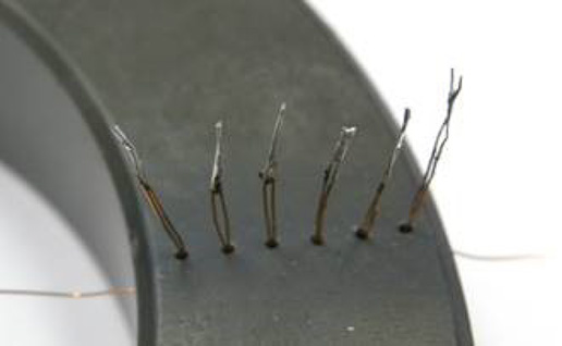
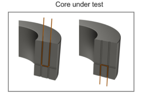
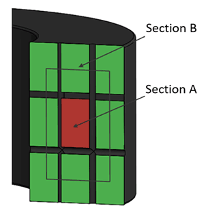
The purpose of the Phase I PSMA-SMA Core Loss projects was to study the flux distribution within ferrite cores while operating. The concept is that a small area internal to the core can be enclosed by a test winding inserted into drilled holes. The voltage on the test windings shows the dφ/dt of the flux.
Initially, eight specially machined cores, two each of four materials, were made by Fair-Rite. Three holes were drilled into each core so that flux in the innermost 1/9th of the core area could be compared to the excitation. These cores were shipped to SMA for study.
Although the original scope was to test these eight cores, SMA drilled seven more 50 mm cores of various materials to provide a larger sample.
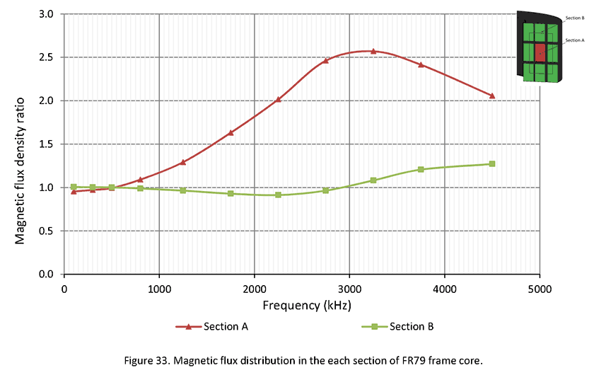
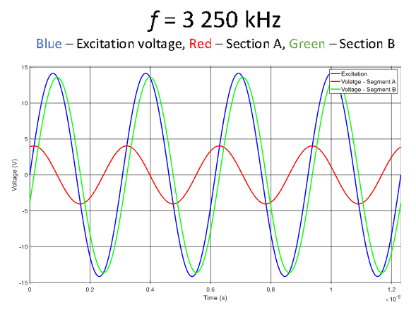
A surprising result for some of the cores was that the flux density in the center of the core was much higher than the average flux density, peaking at just over 2.5 times. Further, it had a large leading phase.
PSMA - SMA special project – Phase II
Phase II was a larger study comprising five parts:
1. Large core testing–flux propagation in ferrites
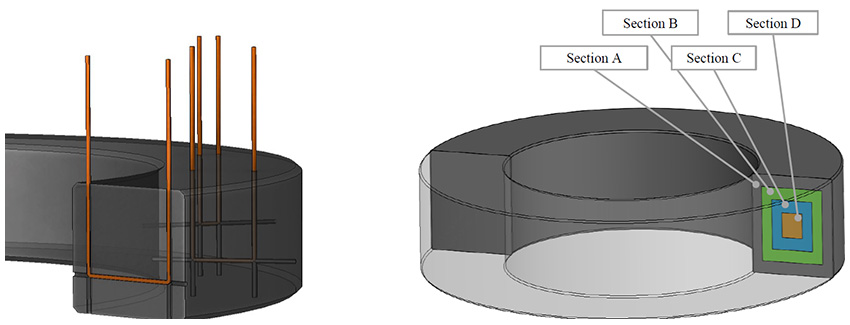
Several large cores were drilled with nine holes so that three sets of wires enclosed progressively smaller internal areas. In this way, the flux and flux density can be measured in three shells and the center for comparison with the excitation voltage.
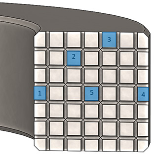
Two other large cores were drilled so that the voltage can be measured around any of 49 segments. Each segment is the same size, 1/49 of the total, so one-to-one comparisons could be made.
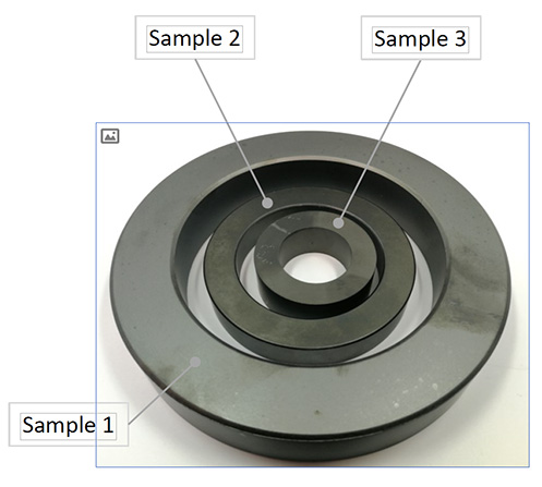
2. Core power loss comparison with different sized cores of the same material.
Large cores of the same material were found to have significantly higher losses when compared on the basis of mw/cm3. This suggests that core loss for different core sizes cannot be calculated based on material specifications, which are usually taken using a "standard" core of about 2.5 cm outside diameter.
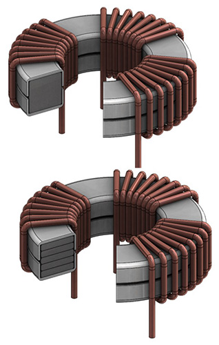
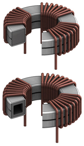
3. Core shape effect on power loss
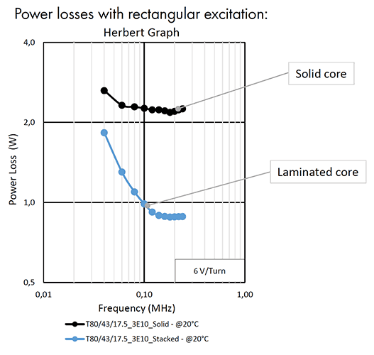
Core losses were significantly lower for a core that was laminated. The second core above has the same area, volume and weight as the first core, but it comprises 5 thinner laminations.
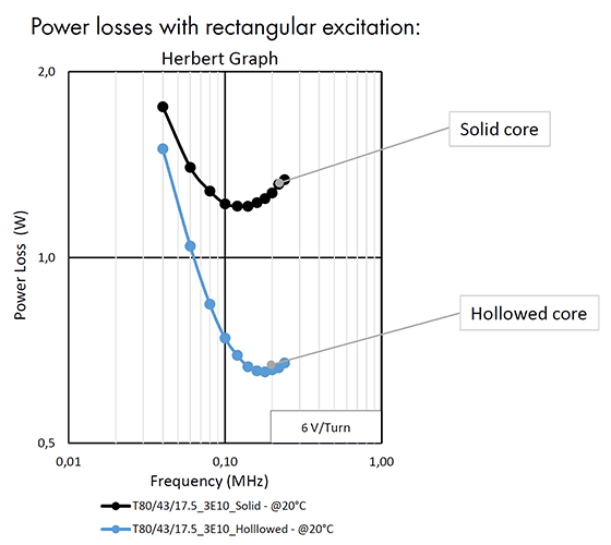
Core losses were significantly lower for a core that was hollowed out. The second core has the same ID, OD and height as the first core. Its area, volume and weight are lower, so higher losses may be expected at very low frequencies.
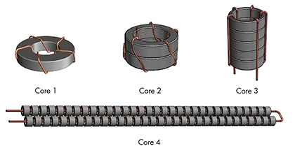
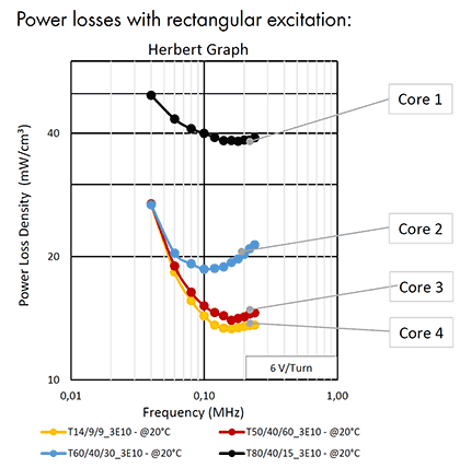
The four cores above all are the same weight and volume. Cores 1, 2 and 3 have the same ID but cores 2 and 3 are stacked and have the same area, volume and weight as core 1. Core 4 has five times the area because it is wound with only one turn, but it has the same volume and weight as the others.
The inductances of the four cores are very close to the same value, as are their other electrical properties except the core loss. The multi-core stacks have significantly lower core loss.
4. Ferrites electrical properties
The electrical parameters (permittivity, permeability, and conductivity) of various ferrites were measured. These must be known accurately to model the core performance successfully.
As an example, Finite Element Analysis (FAE) did not model the observed flux distribution very well using traditional parameters from data sheets. Once the analysis was modified to use accurate parameters, the analysis was greatly improved.
5. Rectangular wave core loss tester
Part of the Phase II core loss program was developing an improved full-bridge rectangular wave driver for core loss testing. The wave shape is determined by an arbitrary waveform generator under software control. The voltage is controlled by a programmable power supply. The time, voltage and current are measured using a high accuracy digital sampling oscilloscope and the parameters are exported to a spreadsheet for post processing and storage. All of the software operations are written in Python.
PSMA Magnetics Committee
In addition to sponsoring these five core loss studies, the PSMA Magnetics Committee continues to be very active. They have organized 5 "Power Magnetics @ High Frequency" workshops in addition to conducting very successful APEC Industry Sessions each year. They also presented two educational webinars as part of the "PSMA Basics of Magnetics for Switching Power Webinar Series" in early 2020. The committee meets about once a month by webconference and anyone interested is invited to participate. Contact the PSMA office at power@psma.com for more information.
Provided by Ed Herbert, PSMA Magnetics Committee Co-Chair
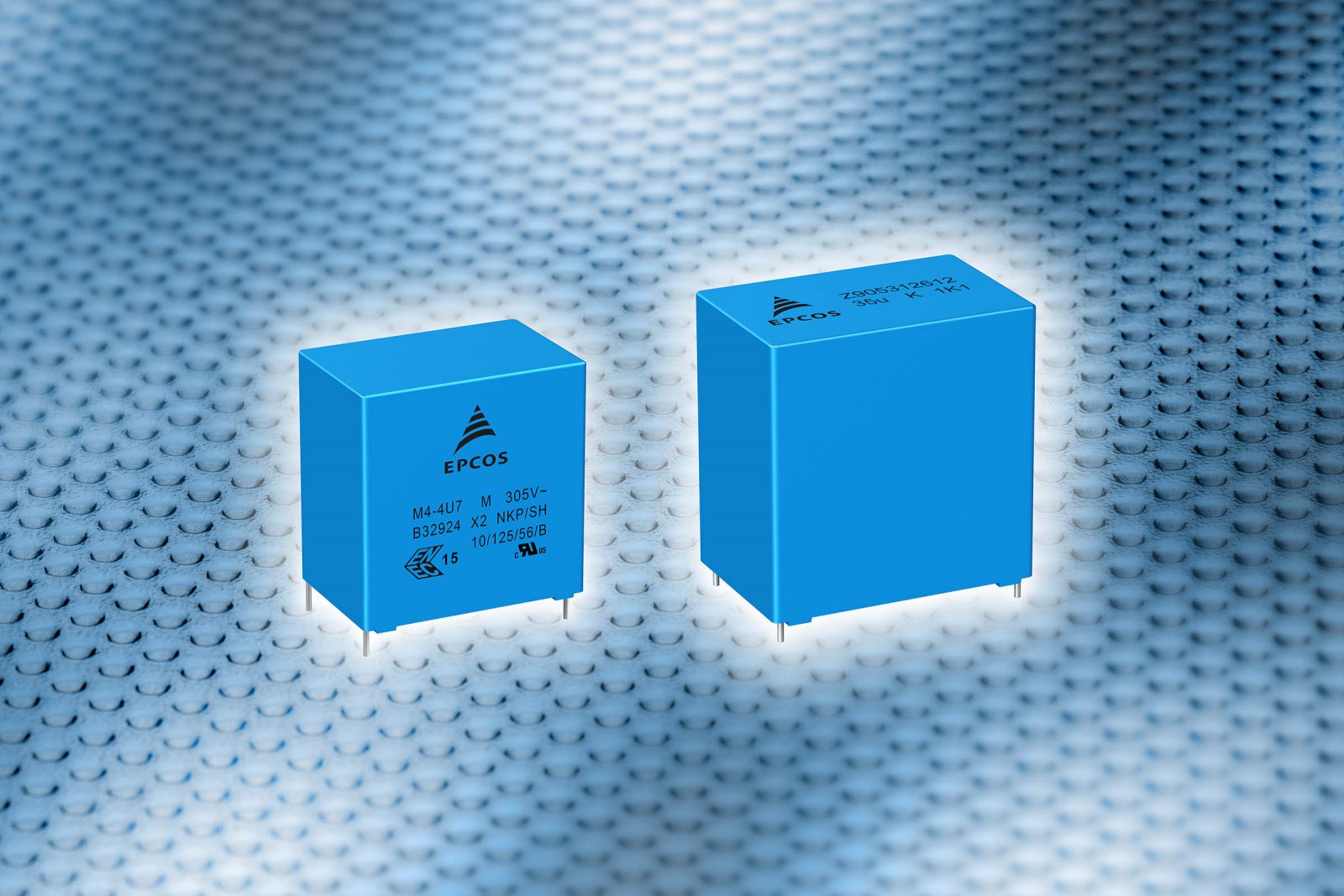 TDK Corporation presents the new, powerful and intuitive CLARA tool (Capacitor Life And Rating Application) for calculating and selecting EPCOS and TDK film capacitors for PCB mounting. The tool offers a versatile parametric search functionality. This includes a search for capacitance, voltage range as well as for rated voltage, RMS and peak current, temperature, maximum dimensions and volume, approvals, reference standards as well as typical applications.






.jpg) TDK Corporation presents a new, user-friendly tool to help users select the right PTC inrush current limiters (ICL) for a range of different power supply and converter topologies. The intuitive tool is available online and does not need to be downloaded. The selection process is divided into four stages: After specifying the circuit structure and the capacitor bank's total capacitance, the developer must then enter the charging voltage and the maximum ambient temperature of the PTC inrush current limiter. After this has been done, the tool displays a list of suitable components for the user, and if a parallel connection is required, the number of components required is also shown. The most important key figures are also shown, as well as links to service distributors that sell the PTC ICLs.
TDK Corporation presents a new, user-friendly tool to help users select the right PTC inrush current limiters (ICL) for a range of different power supply and converter topologies. The intuitive tool is available online and does not need to be downloaded. The selection process is divided into four stages: After specifying the circuit structure and the capacitor bank's total capacitance, the developer must then enter the charging voltage and the maximum ambient temperature of the PTC inrush current limiter. After this has been done, the tool displays a list of suitable components for the user, and if a parallel connection is required, the number of components required is also shown. The most important key figures are also shown, as well as links to service distributors that sell the PTC ICLs.