|
||
|
|
||||||||||
|
PSMA Magnetics Workshop Explores AI, Core Loss | |||||||||||
|
Although presented on the second day, Chema Molina's presentation "Design of Integrated Magnetics using Artificial Intelligence" in a sense set the underlying theme for the workshop. Molina, who is the head of Frenetic AI in Madrid, Spain and did his PhD work at the Polytechnical University of Madrid (UPM), introduced the video for this presentation, which included eye-catching graphics. But graphics aside, this is a subject that easily draws our attention. Integrated magnetics is a hot topic, and AI is everywhere nowadays; why not apply it to magnetics design? With accurate modeling comes involved computation, and design also becomes complicated. A sophisticated magnetics part model under design can be trained with either FEA data or experimental measurements on converters and applied with machine learning to train the model for correct results. That is the basic strategy of the Frenetic AI product, a leading-edge magnetics design tool. Another theme which was dominant throughout the meeting was core power loss. One of the memorable presentations on this topic was given by John Noble of Spang (Magnetics Inc.) who reviewed a major advancement in magnetics materials. A new ferrite named Edge has lower loss with frequency and at the same time has a greater saturation limit. Compared to the advanced nanocrystalline materials, Edge costs less and can be formed into various shapes like other ferrites. Because it has 50% nickel, it is more costly than traditional materials, but less so than nanocrystalline materials.[1,2] Methods for analyzing core loss were also prominent in some compelling presentations. These talks highlighted the shortcomings in the ways magnetics suppliers characterize losses in their cores and the ways that magnetics researchers have attempted to improve the situation. Manufacturers have characterized core loss either graphically, as plots of power loss density, pc( , f), plotted against flux density amplitude, with frequency, f as a parameter, and obtained from experimental data. This quantity is difficult to measure, as one presenter remarked. Ray Ridley and others have also pointed out that the power-loss curves at higher values tend to be in error, on the low side. μ(f) = μ' – j×μ" where inductance corresponds to the real component, μ' and resistance dissipating core loss as μ". Plots of μ' characteristically are flat out to some frequency, then roll off with a linear asymptote, while μ" is near zero at low frequencies, then increases abruptly and peaks near where μ' begins to roll off, then returns to zero. The peak is recognizable as a resonance, and it is, according Marian Kazimierczuk (High-Frequency Magnetic Components, Second Edition, Wiley, 2014) an electron spin resonance in core material. During the first day of the workshop, complex permeability appeared in multiple presentations, and was expounded upon in multiple presentations by the University of Utah professor, Bryce Hesterman, also an advisor to Frenetic AI. He presented his own magnetics model in the form of an equivalent circuit with each winding having an auxiliary winding shunted by a resistance representing core loss, or μ". After describing why the Dowell equation is not valid for certain winding configurations, including multiple windings, he offered an alternative, originally introduced some years ago and refined by him. The resulting equivalent circuit is substantial enough to be represented by a matrix formulation for the model. Hesterman noted a couple of times that the more complete model would include capacitance, which appears to be needed to account for the μ" resonance. However, even with that omission, good agreement with FEA results were reported with this model. The EMI filter theme received attention in many talks including one by Fang Luo of Stonybrook University, whose keynote presentation was about "High Frequency 'side-effect' Mitigation in Power Electronics Converters: Modeling and Integrated Filtering Solutions," which presented an LLC converter example, as did MIT's Mike Kavian Ranjram the next day. In his talk, Ranjram, who is a Phd student working under David Perreault, gave the most intriguing presentation of a catchy idea. Although the basic fractional-turn idea as presented was published in 2017, it was worth repeating and has resurfaced in a 2020 paper, "Leveraging Multi-Phase and Fractional-Turn Integrated Planar Transformers for Miniaturization in Data Center Applications" by Ranjram and Perreault.
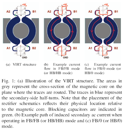
Long ago, Lloyd Dixon of Unitrode (now TI) presented a scheme for constructing a half-turn out of two whole turns connected in parallel. Ranjram refined this idea into the "VIRT" concept shown in the figure below, extracted from the 2017 paper, "Variable-Inverter-Rectifier-Transformer: A Hybrid Electronic and Magnetic Structure Enabling Adjustable High Step-Down Conversion Ratios" by Ranjram, Intae Moon and Perreault. The more recent paper and the workshop talk applied it to planar transformers with two foil windings, each a half-turn per side of the planar E core, a linear variation on the figure. What is appealing about this scheme is that by driving two half-turns with two full-bridge (FB) drivers, the turns ratio can be varied, depending on how the switches are sequenced, to give effective turns of ½, 1, or 2. This multimodal power-transfer circuit scheme also has power-loss advantages from optimizing the turns ratio electronically, like a multi-speed transmission. It also demonstrates how circuit and magnetics design interact. The workshop would have been better in a physical location, but by going to the Internet, the logistics of attendees were greatly simplified. Perhaps in the future, both physical and virtual conferencing can be combined for the optimal selection of attendance mode, depending on attendee circumstances. The PSMA is planning to hold their 2022 workshop in Houston, Texas with physical attendance. For more information, see the PSMA website. References
|
|||||||||||
| <<-Contents | <-Previous | Page 19 | Next-> | |||||||||||
|
If you or anyone in your company is interested in getting on the distribution list for future issues of PSMA UPDATE, please send e-mail to: power@psma.com. Be sure to include your name and
|
|||||||||||