|
 n our roles as chair and co-chair of the PSMA Safety and Compliance Committee, we have hosted a number of Industry Sessions at the Applied Power Electronics Conferences (APEC). These technical sessions focused on isolation and gate drivers for motor drives, power supplies, and industrial applications. In the course of planning these sessions, one of the things we've learned is that there is confusion concerning which standards apply to the various types of optocouplers, optodrivers and isolators used in gate drive and power supply circuits. How do these electronic devices meet safety rules and what are some of the differences between the requirements imposed by the different safety and regulatory agencies?
Besides confusion over which standards apply to isolator devices, there is a general misconception that isolation standards set requirements for isolator performance beyond the input-to-output voltage isolation. For example, isolation standards won't tell the designer anything about transient immunity or propagation delay. This is important because such performance parameters can vary greatly from one isolation device or technology to another.
This leads to another point of confusion regarding isolation standards: even though they are called out on isolator data sheets, these are often not the main standards for most applications, but rather secondary standards. In other words, the isolation standards are called for by application or product requirements such as those for medical equipment, for example. In this article, we review the different isolator device types, identify some of the major isolation standards, and then discuss the requirements imposed on the different isolator device types.
A Quick Survey of Isolator Types
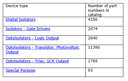
The topic is wide and has many classifications and include a variety of isolator types. To get a sense of the range of devices on the market and the number of different models, we conducted a search of the Digi-Key catalog. The results are shown in Table 1. Although similar searches could have been done on other distributors' catalogs, the Digi-Key search results are fairly comprehensive and provide a good starting point to address the differences among the rules for the various isolation devices. A Quick Survey of Isolation Standards
Next, we did a web search for safety agency compliance standards for isolators. This led us to Application Note 43 from Vishay, which is titled, "Design Guidelines for Optocoupler Safety Agency Compliance". [4] This was just one of many isolator compliance related search results.
The following standards emerged from the search: UL 1577, IEC 61010-1, VDC V 0884-10 (magnetic and capacitive coupler for safe isolation), VDE V 0884-11 (magnetic and capacitive coupler for basic and reinforced isolation) and IEC-60664. IEC-664 (which refers to other standards ending in 664 and which may be harmonized with IEC-60664) defines Installation Categories as indicated in the diagram (see the figure and Table 2), which come from the Vishay application note.
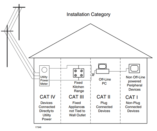
Figure. Installation categories. (Courtesy of Vishay)
|
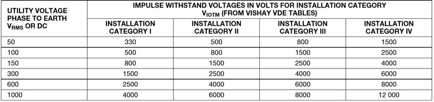
Table 2. Voltage ratings required for the various categories in IEC-664. (Courtesy of Vishay) |
Most appliances and computer equipment fall within Category II while some appliances like cooking ranges are in Category III. A smart meter for utility reading applications belongs in Category IV due to its direct connection to the utility mains. In some applications both an IEC-664 insulation category along with a UL 1577 rating is needed. This all depends on the safety agency defining the test and the end application.
Optocoupler Triac Drivers
One of the couplers used in many home applications and industrial applications is the SCR and Triac driver. Examples include the MOC302x (phase-angle control) and MOC306x (zero-crossing control) families. In this case, UL 1577 applies and there are 1-min. test dc voltages and test ac voltages. These are usually 50 Hz and 60 Hz driving solenoids, heaters, lamps, and some motors. These types of devices have between 2000 Vac and over 6000 Vac between the input and output. The regulating standard has been UL 1577 and the VDE DIN EN60747 standard used in Europe. Design engineers need to look at the data sheet for the various standards of the coupler and the end product standard, which may include EN/IEC 60950 and EN/IEC 60065. White good appliances such as clothes washers, dishwashers, refrigerators, and other appliances often employ these SCR and Triac devices, which are controlled by microprocessors and microcontrollers and used to turn-on drive water solenoids or motors.
Isolators for Switching Power Supplies
Another category of high-volume applications consists of the power supply feedback systems like those employing the 4N35 optocoupler series (6-pin DIP and SMP packages) and the LTV 8x7 photocoupler series (4-pin DIP and SMP packages) which are used with a reference like the TL431 (2.5 V) or the TLV431 (1.25 V). There are also some other references that have a 0.9-Vdc reference voltage. These parts follow the UL 1577 standard—the same standard listed above. The input-to-output voltage rating is between 3750 Vac and 5000 Vac. These types of parts have been around since 1980.
Power Integrations (PI) has a series of flyback power supply parts that do not have an external isolator. These are their secondary-side FluxLink parts like the InnoSwitch-EP (INN2603K). They meet the UL 1577 and the TUV (EN60950) standards and are tested to meet 3500 Vac due to the 100% testing at 4.8 KV ac for 1 second. FluxLink is a high-frequency magnetic feedback system, which was described in the APEC 2018 Industry Session IS04 by M. Hornkamp of PI.[5] This method eliminates the optocoupler. PI also has a series of parts that use the traditional optocoupler and a reference (TinySwitch series). Isolated Gate Driver for Motors and Half-Bridge Drivers
Isolated gate driver ICs for IGBTs, and GaN and SiC transistors used in motor control applications have three different isolation technologies: optical, capacitive, and magnetic. The newer parts use capacitive and inductive coupling across a barrier. They have high dv/dt and common-mode transient immunity, and low propagation delay. All of these isolation devices meet the standard UL 1577, and VDE and IEC ratings defined in the data sheets. Besides the safety standards many of these parts also meet automotive specifications. In addition, many of these components have built-in charge pumps to develop the gate-drive current. That's because the controller is often at a lower voltage than the main power bus, and possibly isolated from the main power bus. With the use of PWM techniques, narrow pulse widths are needed along with very high dv/dt. The high dv/dt can cause the driver to misfire and cause high dissipation in the power switch. This issue was talked about by various presenters in the sessions cited in references 1, 2 and 3. Digital Isolators
Isolators for data signals need both isolation and the ability transmit data at megahertz speeds. These isolators are required by a number of bus standards including Controller Area Network (CAN), SPI, USB, RS485, and I2C bus. Many of these buses have a number of channels and are bidirectional. They use capacitive coupling, magnetic coupling, and, even something known as Giant Magnetoresistive (GMR) coupling. No optical coupling was listed for the high-frequency data rates. Each of these applications require compliance with UL and IEC isolation specifications with UL 1577 being the one most often listed. Summary
All the isolator classifications listed have different performance specifications. Parameters such as signal speed, propagation delay, noise immunity, aging factors, etc. will vary among the different isolation technologies. The one thing they all have in common is that they provide an input-to-output voltage rating similar to UL 1577. The IEC and VDE specifications have similar ratings but, again, these standards are all about specifying the strength of the input-to-output isolation barrier, and not other aspects of isolator performance. The safety ratings do not mean the device will perform per the isolator's data sheet. The design engineer and the various component engineering staff must determine what is required in terms of electrical performance beyond isolation voltage. You cannot use an opto-Triac device where a digital isolator is needed. Since isolation standards are secondary standards referenced by other application or equipment standards, ultimately designers must consult those main standards to determine whether any aspects of those standards will affect their choice of an isolator device. Since the spectrum of application or equipment standards is vast, and access to individual standards requires their purchase, a discussion of what these other standards require of the isolation devices is beyond the scope of this article. References - "Regulatory and Compliance Considerations for Power Electronics," Session IS06 APEC 2017, March 29, 2017.
- "Comparisons and Tradeoffs of Integrated Gate Driver Isolation Technologies," Session IS04 APEC 2018, March 6, 2018.
- "Isolation Topics in Power Supplies," Session IS09 APEC 2018, March 7, 2018.
- "Design Guidelines for Optocoupler Safety Agency Compliance," Vishay Application Note 43
- "Isolation Strategies for High Power" by Michael Hornkamp in Session IS04, "Comparisons and Tradeoffs of Integrated Gate Driver Isolation Technologies," APEC 2018, March 6, 2018.
Authors:
 |
Kevin Parmenter
Director of Applications Engineering
Taiwan Semiconductor America |

|
|
Jim Spangler
President
Spangler Prototype Inc. (SPI) |
Editor's Note: This article was first published in the September 2018 issue of How2Power Today (www.how2power.com/newsletters).
|