|
||
|
|
|||||||||||||||
|
When Peak Power Matters in | ||||||||||||||||
|
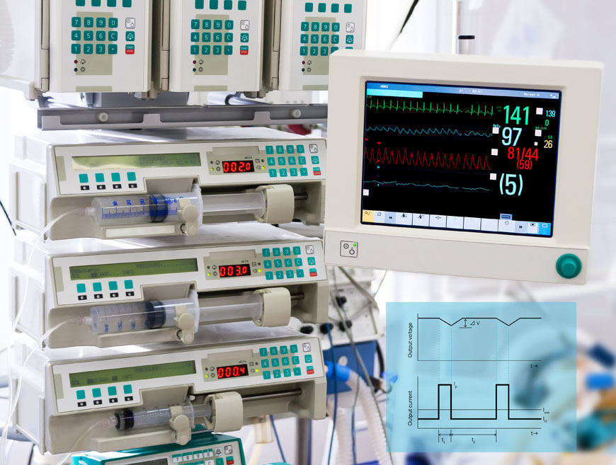
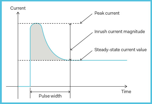
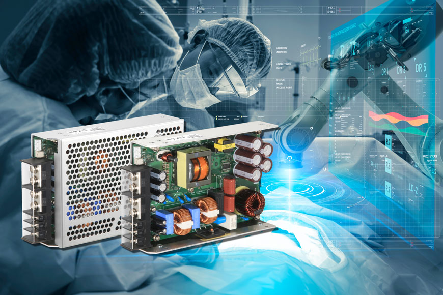
What to consider when a marathon requires sprint race performance? While it is assumed for medical equipment manufacturers that a power supply must comply with safety standards (EN/IEC 60601-1), the output performance is very much dependent on the final equipment's load behavior. While in monitoring and supervising systems the power consumption remains relatively stable and easy to predict, in medical equipment such as medicalized beds, infusion pumps, assisted patient ventilation that includes DC motors, and electromechanical-switches behaving as inductive or capacitive loads, the power supply may at times have to deliver extra power for a period of few milliseconds to seconds (Figure 01). Though the duration time for peak power may be considered short compared to a normal operating time, it still needs to be seriously considered to avoid costly surprises.
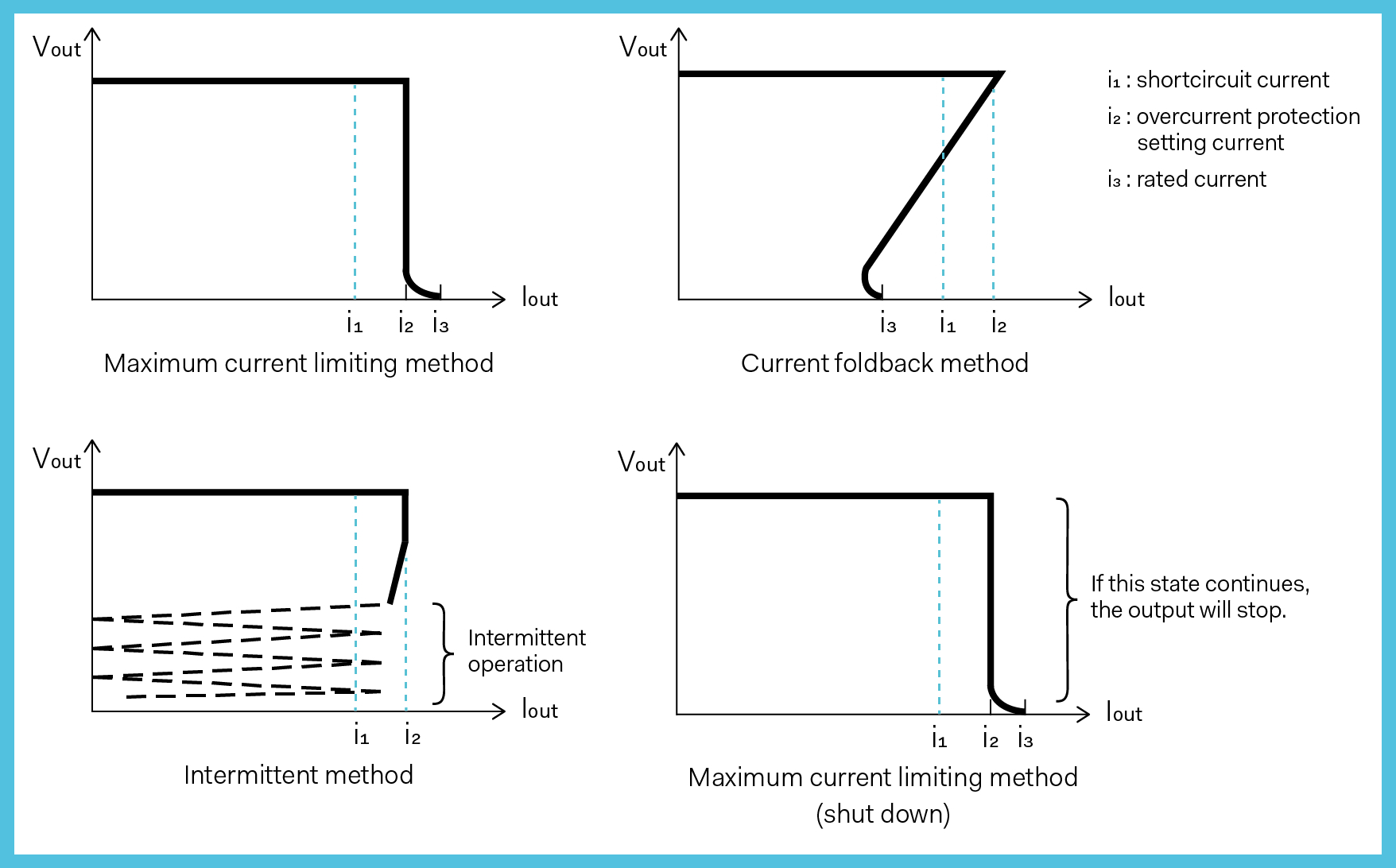
In addition to the output voltage and power, the type of load will determine what factors are important for the system designer to consider. There are many possibilities and in some equipment the main power supply could power a variety of systems and sub-systems with different load profiles which is obviously more complex to address. To simplify, we will list four basic types of loads: inductive, capacitive, constant current, and nonlinear resistive. Each of them has a specific behavior requiring attention when selecting a power supply for each such applications. Loads types in short: Inductive load: Loads such as motors and electromagnetic switches (e.g., relays, magnet switches) with an inductive characteristic are referred to as inductive loads. At the moment of applying a voltage to a DC-motor, a current multiple times the rated value will flow through the load; while at the moment of cutting the voltage off, due to the inductive component of the load, a voltage of counter electromotive force E= -L× (di / dt) will be generated. Generally, when applying a voltage to an inductive load the power supply can sustain the energy required by the peak demand only up the limit of its overcurrent protection (OCP) function (Figure 02). Exceeding the limit, even if only for a very short time, can cause the power supply to stop. This is the reason why the peak load must be well defined in order to select an appropriate power supply with an overcurrent protection that allows the surge power for a definite time and sequence. Also, when turning the output voltage off, due to the counter electromotive force generated (in most cases, it is absorbed by the electrolytic capacitors in the power supply), the overvoltage protection circuit of the power supply may be triggered, and the power supply cease output. In this case measures such as including a reverse voltage protection diode should be exercised. Capacitive load: A load with a capacitance component is called a capacitive load. For example, the capacitors inserted for the purpose of reducing the ripple voltage of the power supply, and capacitors used for coping with peak loads, etc. For this kind of load, at the moment of applying a voltage a very large charging current ipeak = (V/R) with R being the (parasitic) series resistance, will flow due to there being no charge in the capacitor. Although the power supply can detect and control the output voltage, if a large value capacitor (over several tens of thousands of microfarads) is inserted into the output side, such control may not be able to realize what is happening, and the output voltage may become unstable. It is important for system designers to consider the total amount of capacitance installed in their equipment and to verify the power supply's ability to deliver the required peak energy needed to efficiently charge the load which in some applications could be several Farads.
Constant current load: A load where the current stays constant although the load voltage varies is called a constant current load, an example being LED lighting in surgical theaters. It is important to consider the type of overcurrent protection built into the power supply. If for example the overcurrent protection characteristic of the power supply is a current fold back type, the output voltage may not be able to rise (Figure 02). This is because the output voltage stabilizes on the drooping line of the overcurrent protection characteristic of the power supply from applying a voltage to reaching the rated voltage. Generally, by changing the overcurrent protection characteristic to a maximum current limiting type the problem can be solved. Non Linear Resistive: Some equipment uses heating elements or lamps with filaments where the resistance changes when current flows through it. Though this warm up phase with a monotonic resistance change might only last for a short time, for the power supply it may look like a constant current exceeding the threshold value for its built-in overcurrent protection. Overcurrent protection overview
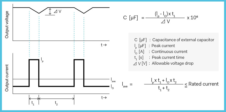
110% is good enough for the vast majority of applications though in the case of demanding medical equipment requiring peak power levels in the range of 200-300% for seconds, 110% will not suffice, requiring a power supply designed not only to deliver a high peak power, but to guarantee the highest reliability during the overall lifetime of the final equipment. Running a marathon at sprint performance levels! This seems to be obvious, but is overkill when the peak is only happening occasionally. For example when a DC motor is activated for positioning a patient's bed then switched off and the power supply is again only powering the control system. Similarly this would be overkill for systems requiring repetitive peak loads for a limited time compared to steady state power. Choosing a power supply for peak load applications requires one to evaluate the operating conditions during the lifetime of the equipment, and to take into consideration all aspects including size, weight and price. Buying a 1200W power supply, when peak load represents only a limited portion of the operation, might not be the best option. Power supply manufacturers have developed power solutions able to deliver significant extra power in the range of twice nominal, or even more than the maximum rated, for a significant duration. This requires the power unit to be designed to host enough capacitors (Figure 04) but also to have a power-train able to sustain repetitive peak demands without over-heating or adversely affecting reliability.
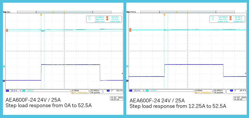
As an example, consider the output voltage behavior of the COSEL 600W AEA600F series (Figure 05) when applying a peak load to the output. The tested product is a 600W rated power unit, delivering 24V at a nominal current of 25A. As presented in Figure 06, the power-train and output capacitors have been selected to sustain a peak power twice nominal for a duration of 1000 milliseconds. Two conditions are represented in Figure 06: From no load to 52.5A peak, and from 12.25A half-load to 52.5A peak. In both conditions, the voltage remains within the specified limits, and OCP is not shutting down the output.
Conclusion References: Powerbox (PRBX): COSEL
|
||||||||||||||||
| <<-Contents | <-Previous | Page 13 | Next-> | ||||||||||||||||
|
If you or anyone in your company is interested in getting on the distribution list for future issues of PSMA UPDATE, please send e-mail to: power@psma.com. Be sure to include your name and
|
||||||||||||||||