|
 s part of my design activities at Spangler Prototype Inc., and as a member of the Safety and Compliance Committee of the Power Sources Manufacturers Association (PSMA), I [James Spangler] was gathering the needed information for future products. These are power supplies that have an EMI filter between the ac line and the switcher. Initially, I had not considered ac power line or lightning transients, so I looked at the PSMA Safety and Compliance website for transients.
I reviewed two IEEE standards: IEEE Std C62.41.2-2002[1] and IEEE Std C62.45-2002.[2] These IEEE standards talk about the voltage spikes, waveforms and surge voltage values that are part of the lightning surges. There are three different types of transient voltages: 100-kHz ring wave, combination wave open circuit (front time=1.2 µs and duration=50 µs), and combination wave short circuit (front time = 8 µs and duration = 20 µs).
Besides the transients produced by lightning, there are other ac line transients to consider. For example, there are transients generated when the utility switches from other feed lines to supply power during electrical power outages. There are also transients generated when high-voltage ac power lines are grounded from falling trees caused by high winds that cause the lines to touch the earth ground.
It is believed that the above IEEE standards consider these events with the various transient waveforms. But there are other standards as well. So, I did a literature search to understand what standards including the IEEE and IEC affect how power supplies protect against such ac line transients. In the process, I gained some perspective on how these requirements were developed. The results of that search are shared in this article.
With that information as background, I then look at the protection elements that are typically in place in ac- dc power supplies. Most of these elements are implemented within the front end section of the power supply that contains the EMI filter. The EMI filter prevents noise generated by the switching action of the power supply from radiating back into the ac mains. But the EMI filter is a passive element and it works in both directions. So, in addition to suppressing noise coming out of the power supply, the EMI filter also protects the power supply from ac line transients.
It's important for power supply designers and users to understand first, how the EMI filter provides this transient protection, and second, whether any changes or additions to this protection are required to meet the regulatory requirements. After dissecting the various protection elements found in the EMI filter, I'll discuss some test circuits that can be used to gauge transient protection performance of a power supply's EMI filter.
Before beginning the discussion about standards, it's necessary to clarify differences in the roles of certain organizations and distinctions between standards, regulations, and the actual product requirements. First of all, governmental bodies like Federal Communication Commission (FCC), United States Department of Energy (DoE), and California Energy Commission (CEC) are the ones that have mandatory regulations. Other bodies like Underwriters' Laboratories (UL), American National Standards Institute (ANSI), National Electrical Manufactures Association (NEMA), International Electrotechnical Commission (IEC), etc. produce standards that are guidelines, unless stated by the governmental regulating bodies like the DoE as required in their regulation. However, it is often the end customer (the purchasing customer) that specifies which standards (IEC, UL, or other) the power supply must meet.
Tracing the Origins of Transient Protection Requirements
The earliest literature I found on ac line transients was from Bell Labs,[3] this was listed in the application note TND335/D[4] reference from ON Semiconductor. The Bell Labs paper was published in March 1961 as it was related to telephone lines.
My best source of ac line voltage transient information is from the GE "transient voltage suppression manual, second edition".[5] When a product is able to survive ac line transients, the product is more reliable; the consumers and owners of the products are satisfied. The information in the GE manual was used to help understand how to protect capacitive drop power supplies for ac-powered smoke detectors and electronic fluorescent lamp ballasts so that they survive ac line transients.
UL 217 Standard for Smoke Detectors[6] has many editions. The first edition was published in 1976, and it had a transient voltage generator circuit. This circuit was built up by Larry Ratzlaff[7] at Fyrnetics of Elgin, IL and used to test smoke detectors and electronic fluorescent lamp ballasts for the ability to withstand input transients from the ac line. (The UL 935 Fluorescent Lamp Ballast Standard[8] did not have any voltage surge test in 1976.)
The generator can produce 6000-V peaks and was used up to 10,000 Vdc for some worst-case test, which was the limit of the tester. This testing occurred during the 1978 to 1980 timeframe. Note that at 10,000 V, any structural wiring that falls within installation categories I through IV, starts to break down, so it's not of much value to design above 10 kV.
But returning to GE's transient voltage suppression manual,[5] (see Fig. 1), we see that it not only provided data on transient lightning strikes; it also provided guidance on what level of circuit protection was needed in the targeted appliances. On page 5 of the manual, it states that "devices (products) that have a 2-kV withstand capability will have a poor service life in an unprotected residential environment. Prudent design will aim for a 3-kV capability. Where safety is of the utmost concern, design for 6 kV that can cope with these rare possible occurrences. The flashover for typical wiring spacing is between 6 kV and 8 kV." (I assume this to be the wall socket).
Looking closer at the graph in Fig. 1, there is a probability that a U.S. household can expect to experience a single 5-kV transient once a year. The first curve points to rural areas with overhead power lines, which could possibly experience a single 18-kV pulse due to lightning. The second curve is the U.S. 120-Vac composite curve. The graph also shows other curves that could be used to gauge the vulnerability of other types of installations to lightning transients.
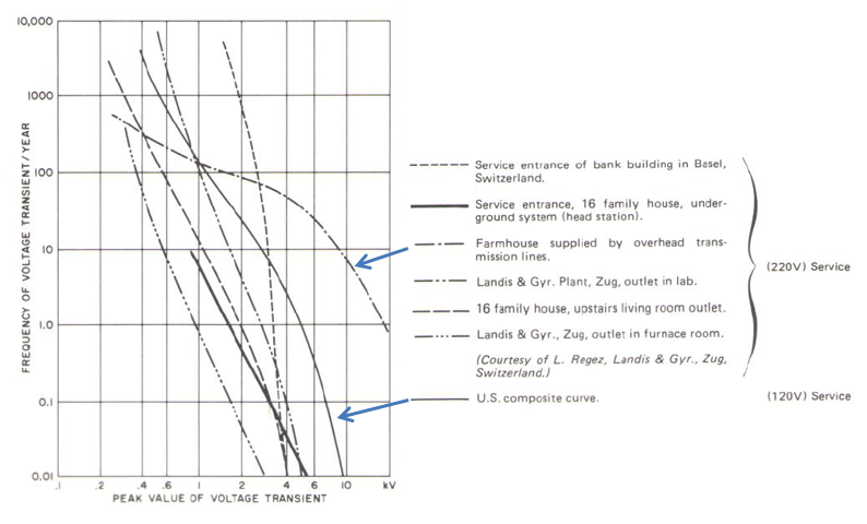
Fig. 1. Frequency of ac voltage transients per year with peak value of transients shown. (Source GE manual, reference [5], page 5, Figure 1.7.) |
The data in the graph was collected in the 1970s, and at that time many products did not experience failures because the power supply consisted of an isolation transformer and linear regulator, which are believed to reduce and absorb much of the transient energy. The transformer construction used silicon steel laminations with copper wire that could limit the secondary current. In addition, the aluminum electrolytic capacitor could absorb energy. The linear pass regulator kept the transient voltage sufficiently low, so the control electronics did not see high voltages that could cause failure.
The GE manual not only provided data on transient strikes, it also provided guidance on what level of circuit protection was needed in the targeted power supplies. On page 5 of the manual,[5] it states: "that experiences with devices (products) that have a 2-kV withstand capability will have a poor service life in an unprotected residential environment. Prudent design will aim for a 3-kV capability. Where safety is of the utmost concern, design for 6 kV that can cope with these rare possible occurrences. The flashover for typical wiring spacing is between 6 kV and 8 kV." (I assume this to be the wall socket.)
Fast forward to the present day and we can look to the IEC 60664-1[9] standard. According to Mark Cantrell[10] of Analog Devices this standard indicates that the IEC transients stop at 12 kV for the low voltage mains. In a recent edition of this Spotlight on Safety and Compliance[12] the following Fig. 2 and Table 1 was published, which defined how the IEC views transients. Another version of this data is shown in Table 2 which is presented slightly differently than the data presented by Vishay's Application Note 43.[12] Scott Aldous[13] presented the data shown in Table 2. (Permission was received from the IEC to use this table).
It can be argued that the old GE Manual and the newer IEC 60664-1[9] are in agreement. Francois Martzloff [14], of GE published "A Guideline on Surge Voltages in AC Power Circuits Rated up to 600V" in 1979 which agreed with the figures cited above along with other information for an 1978 IEEE PES meeting. F. Martzloff gave the same data used Fig. 1 in his presentation along with other information not presented here.
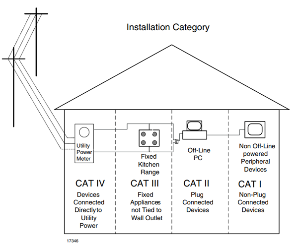
Fig. 2. Installation categories. (Courtesy of Vishay) |
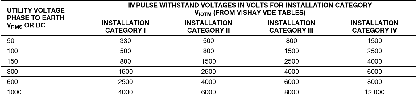
Table 1. IEC 664 table of impulse withstand voltages as presented in Vishay Application Note 43.[12] |
Most appliances and computer equipment fall within Category II while some appliances like cooking ranges are in Category III. A smart meter for utility reading applications belongs in Category IV due to its direct connection to the utility mains. In some applications both an IEC-664, and IEC 60664 insulation category along with a UL 1577[15] rating is needed. This all depends on the safety agency defining the test and the end application.
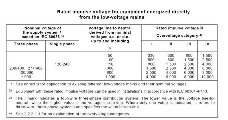
Table 2. Another presentation of what is essentially the same data from IEC-60664-1, Ed.1.2.[9] (Permission was received from the IEC to use this table.) |
Today the linear regulator power supply system has been replaced with an electronic switch mode power supply. The lightning transients are still present as shown in Fig. 1. The devices that limit the transients are discussed below.
Transient Protection In AC-DC Power Supplies
Today most of the power supplies are of the switch-mode type with an ac-dc section as shown in Fig. 3. This figure will be used to discuss the elements that suppress transient voltages and limit the surge current that can destroy the control electronics in a piece of equipment and cause a product failure. The earth ground is not shown in the example since most of the lightning and transient voltage and current flow on the ac hot and ac neutral.
It is true, however, that if there is a lightning strike near a building, there can be a rise in ground voltage. But in many cases, the ground rise voltage will also be on the neutral since both the neutral and earth ground (safety) are tied together at the service panel.
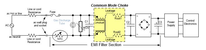
Fig. 3. The front end of a power supply. |
Input Protection C1, MOV, And Gas Discharge Tube
When there is a voltage transient on the ac supply lines, in most cases, the first device providing protection is the metal oxide varistor[5,16,17] (MOV). An exception to this would be if the control electronics are part of a medical device. In that case, the first item might be a gas discharge tube or spark gap (not shown).
In Fig. 3, we see that there are three devices in parallel that can limit the lightning or voltage transient—the MOV, an X rated class capacitor, and a common-mode choke. The breakdown or clamping voltage of the MOV is normally 1.5 times the peak of the ac line voltage. The breakdown voltage for an MOV is specified when a 1-mAdc current flows through the device. Both Littelfuse and Vishay have application notes on the selection of the voltage for varistors. C1 is an X class capacitor specified for ac line operation. Both MOVs and gas discharge tubes[18] take time to operate, so downstream elements like the common-mode choke, C2 and C3 need to be able to absorb energy.
Included is the resistance of the power leads from the service panel or fuse box to the product and the hot resistance of the NTC surge limiting thermistor[19] for limiting surge currents during transients and turn-on power. The resistance and capacitance of the building electrical supply distribution system is built-in and assumed in the IEC-specified Installation Classes for the equipment. This reduces the peak energy of the power line disturbance.
For example, a utility watt-hour meter (Smart-Meter) that is connected upstream of the panel would need a reinforced transient rating for a 120- to 240-Vrms single-phase line of 6000 Vpeak. This is Installation Class IV. But a device plugged into an outlet within the building, which is Installation Class II, would need to be rated for 2500 V. The evaluation of the EMI input filter and protection should be near 2500 Vpeak and not reduced further by line impedance, per Tables 1 and 2 above.
The supply wiring resistance can be considered small but this resistance limits the current if there is a 6-kV to 8-kV power type transient. The longer the line and the smaller the wire diameter the greater the limiting effect. In many Smart-Meter applications, there is a gas discharge tube which can be used to limit the voltage. A Smart-Meter (utility watt-hour meter) is installed prior to the service panel and is considered an Installation Category IV. Gas discharge tubes (GDTs) have a follow-on current until the next ac zero crossing of a transient. This may cause a nuisance blowing of the fuse. If a GDT is used, the fuse should be a user-replaceable type.
Common-Mode Choke
The common-mode choke is the next device that helps limit the lightning transients. Besides the mutual inductance, there are leakage inductances on each leg. The leakage inductance (shown as a dashed line in Figs. 3 and 4) can be a single device or split into two devices. The leakage inductance is a differential-mode inductance. Some designs have separate inductors.
The coil resistance of the common-mode filter is very important and serves two purposes: first is to help limit some of the transient surge current, and second is to limit the inrush current when the ac power is first applied. The full bridge diodes have a peak surge current rating and the coil resistance helps limit the inrush current seen by the diodes. In cost-sensitive designs, the common-mode choke resistance can eliminate a special negative temperature coefficient NTC resistor to protect the diodes in the full-wave bridge from inrush surge current.
C2 and C3
The capacitors C2 and C3 absorb voltages that are not stopped by the other elements. C2 is an X rated class capacitor placed across the ac line. The rise time of the voltage is reduced by the combination of inductance of the common-mode filter, C1, C2, and C3. The slower surge rise time, which is lower in frequency, and is rectified by the bridge rectifier, causes the voltage on C3 to rise. The rise above the normal depends on the capacitance value of C3. A power factor correction (PFC) circuit can be inserted between the bridge rectifier and the power supply box shown in Fig 3.
Lightning Surge Testing
In 1978 during the development of the electronic fluorescent lamp ballast, lightning surge testing was performed on a number of designs using the voltage transient test circuit described in UL 217. All of the designs tested had an EMI filter and a PFC circuit. The EMI filter was required in order to pass the FCC Part 15 and Part 18 specifications. All of the systems survived the testing without any apparent damage to the power switches.
Two additional pieces of information might be of interest; both of these are shown in Fig. 4. The first item is a pc board slot to prevent arching over the board surface. In compact, small power supplies like those used in USB cell phone chargers, slots are being used to add spacing between components to meet isolation voltage requirements. In electronic ballast designs, the board had a conformal coating, which allowed closer spacing of input components and no slots were used.
If the capacitance values of C1 and C2 are large, they may hold a charge and be a source of a shock hazard. These parts need to be discharged so the consumer does not receive an electrical shock if they happened to touch the power cord plug blades. One solution is to add a newer component from Power Integrations called a CAPZero[20] as shown in Fig. 4.
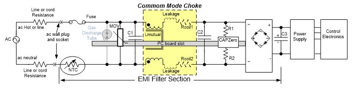
Fig. 4. PC board slot and discharge of C1 and C2. |
Application Circuits
In writing this article a quick search was made for application circuits that test for transients. Power Integrations[21] has published a number of circuits with construction techniques, line conducted EMI test results, and line surge testing. Please review the Power Integrations information given on page 49 of DER-535[22], which shows a lighting surge test for a 65-W power supply design. An EMI line conducted test is also in the document. The test results are repeated here in Table 3.
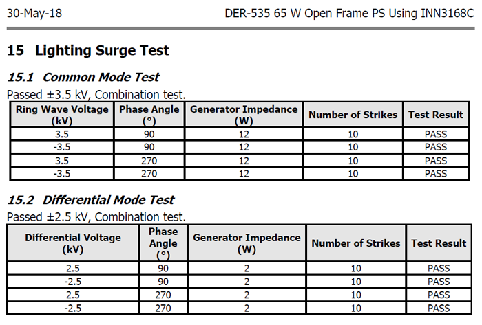
Table 3. Lightning Surge Test for DER-535 application board. |
In addition, look at DER-613[23] on page 87 for details on line surge testing of a 27-W USB charger design. Test results are repeated here in Table 4. This document also shows EMI line conducted test results.
Conclusion
All switching power supplies have some sort of EMI filter. This filter is a passive filter and is bidirectional. The EMI filter prevents noise from escaping from the power supply and prevents various power line surges from entering the power supply.
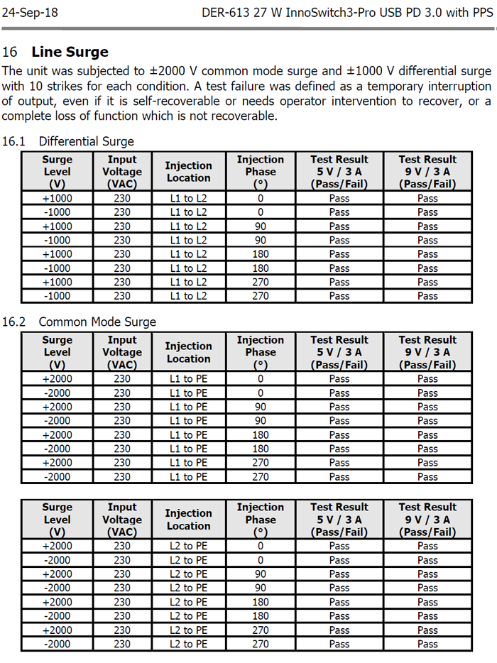
Table 4. Line Surge test results for the DER 613 applications board. |
There are two IEEE standards that should be reviewed: IEEE Std C62.41.2-2002[1] and IEEE Std C62.45-2002[2]. These IEEE standards talk about the waveforms and transient voltage surge values. There is another document: IEC 61000-4-5[25], that describes similar ac power line transient tests.
It is important to test your power supply with the EMI filter in place. Test the power supply system for transients and surges to see what level the unit passes before making changes to your circuit. You may be surprised that the EMI filter did all the work and no additional components were needed to pass the voltages of 4 kV peak.
I wish to thank Dave Pacholok[24] for his assistance, providing several references, and a review of this article.
References
- IEEE C62.41.2-2002 - IEEE Recommended Practice on Characterization of Surges in Low-Voltage (1000 V and less) AC Power Circuits.
- IEEE C62.45-2002 - IEEE Recommended Practice on Surge Testing for Equipment Connected to Low-Voltage (1000 V and less) AC Power Circuits
- "Lightning Surges in Paired Telephone Cable Facilities" by D.W. Bodle and P.A. Gresh, The Bell System Technical Journal, Vol. 4, March 1961, pp. 547-576 (available from IEEE on request).
- "Transient Overvoltage Protection", TND335/D, On Semiconductor, April 2008.
- Transient Voltage Suppression Manual. 2ed, copyright 1978, GE Technical Information Exchange, Schenectady, NY 12301.
- UL 217 Standard.
- Larry Ratzlaff
- UL 935, Fluorescent Lamp Ballast Standard,
- IEC-60664-1.
- Mark Cantrell, phone conversations Aug, Sept, and Dec. of 2018.
- "Isolation Standards Say Little About Isolator Performance" by James Spangler and Kevin Parmenter, How2Power Today, September 2018.
- "Design Guidelines for Optocoupler Safety Agency Compliance," Vishay Application Note 43
- "Product Safety Considerations for Insulation Coordination of Low-Voltage Equipment" by Scott Aldous, Advance Energy.
- "A Guideline on Surge Voltages in AC Power Circuits Rated up to 600 V" by Francois Martloff, General Electric Company, Schenectady NY, Proceedings, 3rd International Symposium on Electromagnetic Compatibility, Rotterdam 1979.
- UL 1577 Standard for Optical Isolators.
- "Selecting a Littelfuse Varistor," Application Note AN9771.1, July 1999.
- "The ABCs of MOVs-Littelfuse," Application Note 9311.
- Gas Discharge Tube, Littelfuse,
- Thermistor.
- CAPZero.
- Power Integrations design examples.
- DER-535 Power Integrations
- DER-613, 27 Watt USB.
- David Pacholok.
- IEC-61000-4-5 › Electromagnetic compatibility (EMC) - Part 4-5: Testing and measurement techniques - Surge immunity test.
Authors:
 | Kevin Parmenter
Director of Applications Engineering
Taiwan Semiconductor America | 
| | Jim Spangler
President
Spangler Prototype Inc. (SPI) |
Editor's Note: This article was first published in the December 2018 issue of How2PowerToday (http://www.how2power.com/newsletters/index.php).
|